Elevators 101: Don’t Slip Up on Rope Configurations
If you’re not an elevator aficionado but want to hold your own in a conversation with your technician, you’ve come to the right place. Not only do we provide a glossary filled with simple explanations of common elevator terms in Classroom On Demand, our new Elevators 101 blog series provides more in-depth information for eager elevator experts-to-be.
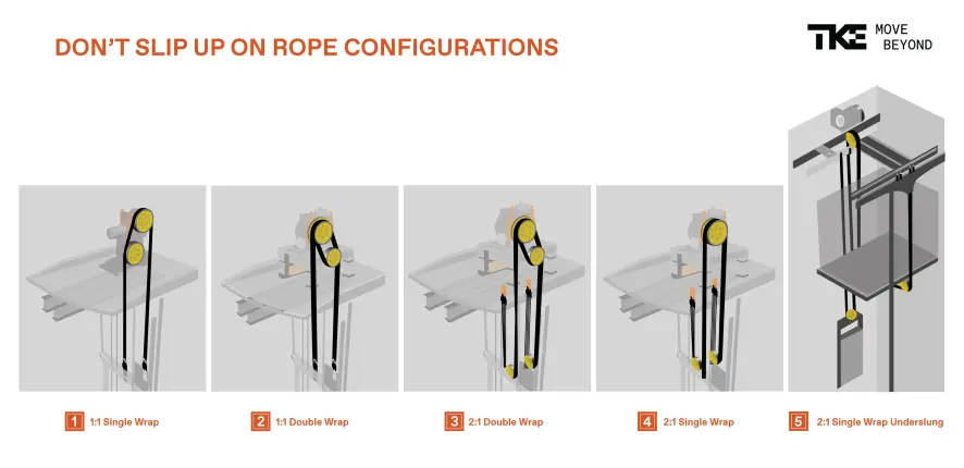
Our goal is to help you understand more about vertical transportation without having to decipher unfamiliar lingo in a hefty textbook. By the end of this blog, you can be sure you’re up to date with the latest in rope configurations.
Without further ado, let the class begin!
What Are Rope Configurations?
We’re so glad you asked! First, it’s important to note that this article only discusses traction elevators that use these typical rope configurations, sometimes referred to as roping arrangements. Given that traction elevators operate on a counterweight and pulley system, unlike the hydraulic elevator, wire ropes (AKA cables) or flat belts are vital to their function. And these ropes must be made of the best quality steel to ensure optimal performance.
Secondly, the ropes are held in place by a piece of equipment called the sheave which rotates the ropes to successfully move the elevator cab up and down. The word “traction” is defined as the adhesive friction of a body on a surface on which it moves. Without the ropes passing over the sheave and the counterweight helping to balance it all, there is simply no traction. This is where rope configurations come into the picture.
Rope configurations are ways ropes are wrapped around the sheave to improve elevator functionality. The reasoning behind a variance in configurations comes down to the fact that elevator design is not always straightforward with one sheave and one counterweight. Often, elevators will need secondary sheaves or deflector sheaves to offer the cab some space further away from the counterweight or add more traction to the system.
Omar Newsome is a Senior Technical Instructor at TK Elevator. He provided some great insight into how roping configurations can change an elevator system: “Think of roping configurations much like a pulley system, because fundamentally that’s what they are. We have several different options in ‘pulley systems’ or roping configurations to choose from to best fit the customer’s need and building configuration. One example, 2 to 1 roping allows us to lift an impressive amount of weight with an elevator motor that fits in the overhead, saving valuable square-footage.”
Keeping Omar’s example in mind, let’s take a look at the differing arrangements and why your elevator could need to be set up this way.
1:1 Roping Single Wrap
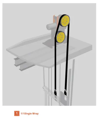
This is for low-rise elevators and, in some cases, mid-rise elevators. It’s a pretty straightforward layout like we talked about earlier.
This configuration is used for low-rise, low-speed elevator systems, but if a gearless machine is used, then higher speeds can be attained. The cab counterweight and hoist ropes all travel at the same speed. One end of rope is connected to the car and the other end is connected to the counterweight. The rope travels over the machine sheaves. In this case, the rope is diverted to a distant opening by the deflector sheave.
1:1 Roping Double Wrap
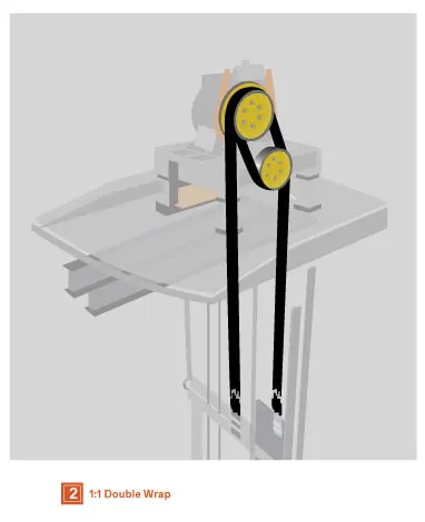
Those taller buildings you see in the city? Those are going to need a double wrap. This configuration is used for high-speed gearless applications because the double wrap is needed to create more traction (friction) and also minimize rope wear. The ropes from the car shackles are wrapped around the drive sheave, around a secondary sheave, and then back around the drive sheave to end at the counterweight shackles.
2:1 Roping Double Wrap
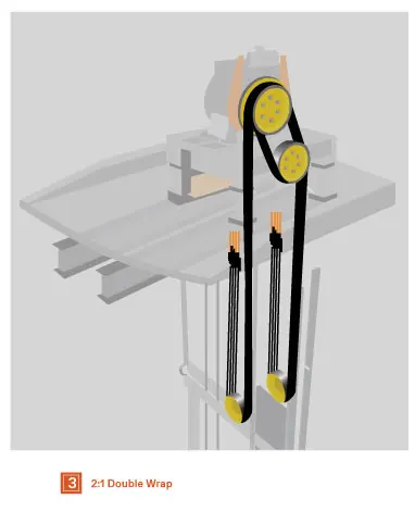
This configuration is good for high-speed gearless traction elevators. The hoisting ropes pass over a secondary sheave and back over to the drive sheave again, thus the traction (friction) of the ropes on the drive sheave is increased. One end of the ropes then pass through a car compounding sheaves attached to the car and the other end then passes through a counterweight compounding sheave to the counterweight.
In this configuration, the car speed is half the rope speed, meaning the motor must rotate twice as fast as a 1:1 configuration. Please also note that the drive sheave and secondary sheave are wider because you need twice as many grooves for the ropes to pass on.
2:1 Roping Single Wrap
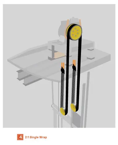
In machine room-less elevator applications, a 2:1 single wrap can be applied on both geared and gearless machines. This arrangement provides traction using the grooves in the sheave that will pinch the ropes with varying degrees of pressure depending on the shape of the groove and its undercutting. It should provide 180 degrees of rope contact with the sheave regardless of the use of a deflecting sheave.
2:1 Roping Single Wrap (Underslung)
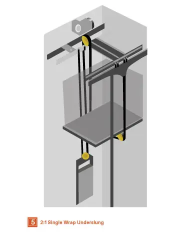
This is another gearless traction application like the previous roping configuration except the ropes will be fed under the elevator car through sheaves attached to the underside. Hence the name “underslung.”
Vibration isolation pads are added between the car sheave assembly and elevator car to minimize any vibration associated with the rope and sheave movement and improve the ride quality. It will also provide additional workspace for the technician on the car top in machine room-less applications, leaving ample room to maintain the overhead equipment.
Though this is the last roping configuration we will be discussing, these can get as massive as 5:1 for large freight traction elevators. We are glad you joined us to go through the most common ones you will see. Until next time, we wish you happy elevatoring!
 United States

